James Roy, Yacht Design Director at BMT Nigel Gee, a subsidiary of BMT Group Ltd, the leading international maritime design, engineering and risk management consultancy, draws from his experience in the design of numerous superyachts and commercial vessels to explore the practical limitations of optimising superyacht hulls. Together with his colleague, Naval Architect Rob Sime, they provide insights and reasoning for the process differing from that in the field of commercial vessel design.

A properly optimised bulbous bow can offer significant savings
Operating costs and fuel costs in particular are the biggest driver in the commercial vessel market. The desire to reduce these costs has always provided a focus for the optimisation of the vessel’s hull to develop efficient ships with minimal powering requirements; even a significant investment in hull form optimisation at the design stage can quickly achieve a payback.
Large yachts however spend far less time at sea than commercial vessels and consequently, for an average yacht, fuel costs represent a far smaller proportion of annual operating costs. Additionally for those who own and operate these yachts the adage that, “If you have to worry about filling her up then you probably can’t afford it” holds true and cost is in general not an issue. However with rapidly increasing fuel prices, ever more stringent environmental legislation and the desire to be seen to be green, there is increasing focus in the superyacht industry to improve efficiency.

An optimised 85m yacht about to undergo physical testing
Large yachts tend to have relatively high hotel loads and, given the relatively low hours at sea, much of today’s focus within the industry is on reducing generator fuel burn through energy efficient technologies. However hull efficiency remains a very significant part of the overall through life efficiency, and whilst optimisation of a yacht hull is often undertaken, it is typically compromised by other factors relating to the functional aspects of the design. It is these factors that present different challenges to the optimisation of a commercial vessel.

Flow Visulisation Tests
BMT Nigel Gee undertakes optimisation across both the yacht and commercial vessel industries. Critically our work is not limited to the pure naval architecture of the optimisation process but also to complete vessel design and engineering (from concept through to delivery) allowing valuable insight into how the processes differ between yachts and commercial vessels. BMT Nigel Gee chooses to adopt a methodical approach in developing a hullform. This makes use of optimisation techniques predominantly based on experience, married with an appropriate level of computational analysis. With modern computer techniques it is very easy to launch into the generation of 3D lines too early in the process without sufficient focus on a formal optimisation methodology. Additionally the use of Computational Fluid Dynamics (CFD), whilst of significant potential value, has its limitations. Where utilised, such techniques must in our experience be tempered with optimisation variable limitations specific to large yachts gained from practical experience, some of which will be cited as specific examples in this article.

Generic image - hull lines plan in blue print
Our hull design process begins with three critical parameters; displacement, length and speed. The latter two variables define the Froude number which gives an indication of the basic hull type, where to set our goals and how challenging they will be to achieve. With a commercial vessel there will be a well defined operating profile with target speeds often derived from analysis of required transit times or freight rates vs. optimum voyage speed analysis. This is not so for yachts where the cruising speed and maximum speed are often decided upon by the captain or the owner. Additionally there is no defined, or even typical, operating profile to apply so deciding the optimisation point in an analytical manner can be very difficult. It is also often the case that the maximum speed desired may be subject to one-upmanship resulting in a large difference between the cruising speed and the maximum speed, further complicating the optimisation process.

Generic image - hull lines plan.jpg
With a well executed project, part of the job of the naval architect is to try and influence the owner’s decisions to bring the target speeds and optimisation point to sensible parameters. This is often a difficult job!
The third variable in our initial assessment is the displacement in relation to length and the next step is to undertake an assessment of the yachts overall design concept. Is the vessel a slender, low volume design or a beamy, high displacement motor yacht? These factors have a critical influence on the direction that we follow, as displacement in relation to length is the most influential parameter on resistance.
With a commercial vessel the naval architect will be in control of the design intent behind the concept. This is rarely the case with large yachts where the stylist (aka the Yacht Designer) will have defined the design intent and many of the defining features of the yacht. These will have already been laid down and “sold” to the owner. It then becomes the job of the naval architect to work with the stylist to try and maintain as much of that design intent whilst quantifying the compromises that may have to be made in order to improve the hydrodynamic efficiency of the overall design.
")
Optimisation of appendage alignment (Roll Fins)
Additionally at this stage we will undertake a preliminary stability assessment in order to confirm that the beam, often already decided by the stylist, will be acceptable. In conjunction with this, preliminary powering estimates will also be made to verify the space reserved for the main machinery space.
Following the initial assessment we set target values for the optimisation of key form coefficients and parameters including block, prismatic and maximum sectional area coefficients, longitudinal centre of buoyancy and floatation, wetted surface area and immersed transom area. If a bulbous bow is to be used the basic parameters are set down; bulb type, centreline profile shape, sectional area and immersion. Additionally the effects of appendage and propulsion system integration are considered including propeller diameter, tip clearance and rudder configuration amongst others.

Optimisation of bulbous bows using Computational Fluid Dynamics
It is normally at this point that many of the aforementioned features of the stylist’s design intent start to present barriers to effective optimisation. Two examples spring to mind. The first is a 100m motor yacht where the arrangement of the design had been centred around a central vertical ‘feature’ staircase running from the tank deck right to the sky lounge of the yacht. The longitudinal location within the yacht was fixed by the stylist and considered immovable. The end result of this was that the engine room had to be pushed relatively far aft in the design, resulting in a less than optimum LCB, form coefficients and steep buttock angles, all contributing to an increase in resistance. The second example was an 85m motor yacht where the design featured a large swimming pool in the aft lazarette (commonly called the ‘beach club’ on large yachts). In order to accommodate this, and integrate the shaftline, the hull had to be deepened aft resulting in increased transom area and non optimal LCB: The consequence of which was a significant increase in vessel resistance and reduced propulsion coefficients.
The next step in our process involves optimisation of the sectional area curve. This is an exercise which is often forgotten but achieving the correct area profile is critical in achieving a set of hull lines which combine the desired characteristics with efficient hydrodynamic performance. We will generally start with the sectional area curve for a basis yacht such that we have a known and quantified baseline. Once the sectional area curve has been developed to our satisfaction we can modify the parent lines to obtain the optimum midship section shape and area distribution.
At this stage we must also consider further practical constraints which limit our ability to achieve the desired sectional area shape. Many of these are common to both commercial vessels and yachts alike, such as integration of the selected propulsion system. However some are in general limited to yachts only, for example roll fins on yachts are designed for operation at zero speed. In the absence of hydrodynamic lift they generate the required righting moments by being over sized (typically 30-40% greater area than conventional roll fins) and operating in a paddle fashion. These large fins are often constrained in their longitudinal position by internal arrangements and frequently present a serious challenge to integrate within the beam-keel envelope whilst maintaining an optimised sectional area curve and undistorted waterlines.
Bow thrusters are another common challenge on yachts. Typically, in an attempt to maximise internal volume for accommodation, they are pushed very far forward in the general arrangement. This can lead to fuller forebody waterlines and sections with the resulting half angle of entrance being increased significantly to achieve the minimum required tunnel length.
Having developed set of lines optimised to the principal parameters, as far as possible, within any accepted compromises, the next step in our process involves more refined consideration of section shapes, waterline shapes and buttocks. Generally by this stage we will have a clear idea of the mix of characteristics we are looking to incorporate; partial propeller tunnels, required return in stern buttocks and forward waterline curvature are all parameters which we optimise at this time. The use of CFD can be useful at this stage to compare the impact of subtle refinements and to assist in positioning appendages such as bilge keels or to study theoretical flow patterns in areas of special consideration.
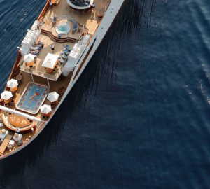
An excellent example of a design where efficiency has not been overly compromised by function is the 73m motor yacht Silver (2008). In this case the GRT of the design (internal volume, and therefore function) has been restricted in order to save weight resulting in an internal volume of only 60% of a typical 73m. The result is that a high length beam ratio can be adopted together with a high length displacement ratio. This resulted in the vessel achieving a 27 knot maximum speed with only modest levels of propulsive power. It is evident in this design that the owner has accepted fewer functional luxuries in order to achieve a fundamentally efficient design; less accommodation space, no helicopter pad, no large swimming pool etc.
The optimisation of a yacht hull is beset with challenges, many beyond the control of the naval architect. In the interest of ensuring efficient hydrodynamics, BMT Nigel Gee attempts to manipulate the yacht’s layout such that the impact of these constraints are minimised allowing the highest level of optimisation to be achieved. However the dynamics of the particular project, relationships and parties involved often means that on many large yacht projects significantly higher levels of compromise are required than would be expected for a commercial vessel. Educating the client and stylist in a quantified manner as to the impact of compromise is as much part of the design process as the naval architecture. Ultimately it is up to the client to decide how much compromise they are willing to accept but involvement of a naval architect at the very early design stage of a project will ensure that the hydrodynamics and design intent of the stylist can be harmoniously integrated with minimal compromise.